
Features

The engineering, in detail.

What PileAxis computes for a drilled shaft, a precast pretensioned pile or a steel H-pile, the methods and standards it follows, how it has been checked, and where it stops. The built-in manual explains every method and equation so you can verify the results yourself.

Pile systems

One deep foundation element, three ways to build it.

Each pile analysis in a project chooses its pile system on the Pile tab. The lateral and axial solution is the same for all three; the section check and the axial capacity follow the pile system, each to the standard that governs it.

  • Free

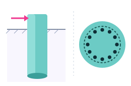
    Drilled shaft or caisson

    A circular cast-in-place reinforced concrete pier, uniform along its length. Section strength to ACI 318-25 on a Mander-confined fiber section; axial capacity by the FHWA drilled-shaft methods.

  • Pro

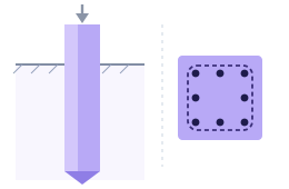
    Driven precast pretensioned pile

    The PCI standard square and octagonal piles, solid or voided. ACI 318-25's prestressed provisions, PCI's spiral and driving-stress checks; axial capacity by FHWA GEC-12.

  • Pro

    Driven steel H-pile

    AISC HP shapes from the catalogue or custom plate dimensions, bent about the strong or the weak axis. AISC 360-22 member checks; axial capacity by FHWA GEC-12.

Analysis · Free

Lateral and axial response, solved together.

The pile is a beam on nonlinear soil springs: p-y springs for the lateral response, t-z springs along the shaft and a Q-z spring at the tip for the axial response, solved together so the axial load's effect on bending is carried through.

Numerical method

Free

A layered p-y solver

  • The coupled axial and lateral formulation of Naik and Peyrot for piles and caissons in layered soil
  • Finite differences on a banded matrix, solved in time proportional to the number of nodes
  • Newton-Raphson iteration with a backtracking line search for robust convergence
  • A uniform mesh, or a graded mesh finer near the head where the curvature is greatest, with every layer interface and the water table on a node
  • An outer loop that updates each node's stiffness from the section's moment-curvature response

Boundary conditions

Free

Heads, tips and the axial load

  • Free or fixed heads, with a head shear, moment and axial load per combination
  • Free, pinned, fixed or spring-supported tips; the base springs derived from the p-y response or entered by you
  • The axial load's P-delta moment carried through the head and tip shear as well as the interior
  • A guide to choosing them by the pile's length relative to its stiffness, in the manual

Every run reports

Free

The whole pile, for every load combination

  • Profiles of deflection, bending moment, shear and soil reaction, and of settlement, axial force and unit skin friction, along the whole embedment
  • Demand-to-capacity ratios for axial force with moment, and for shear, at every node
  • The governing case found separately for section strength, for soil capacity, and for deflection and settlement
  • Every enabled combination solved at once in parallel, each on its own copy of the pile, with no limit on the number of combinations

Soil · Free

Nine soil models, layer by layer, under a water table.

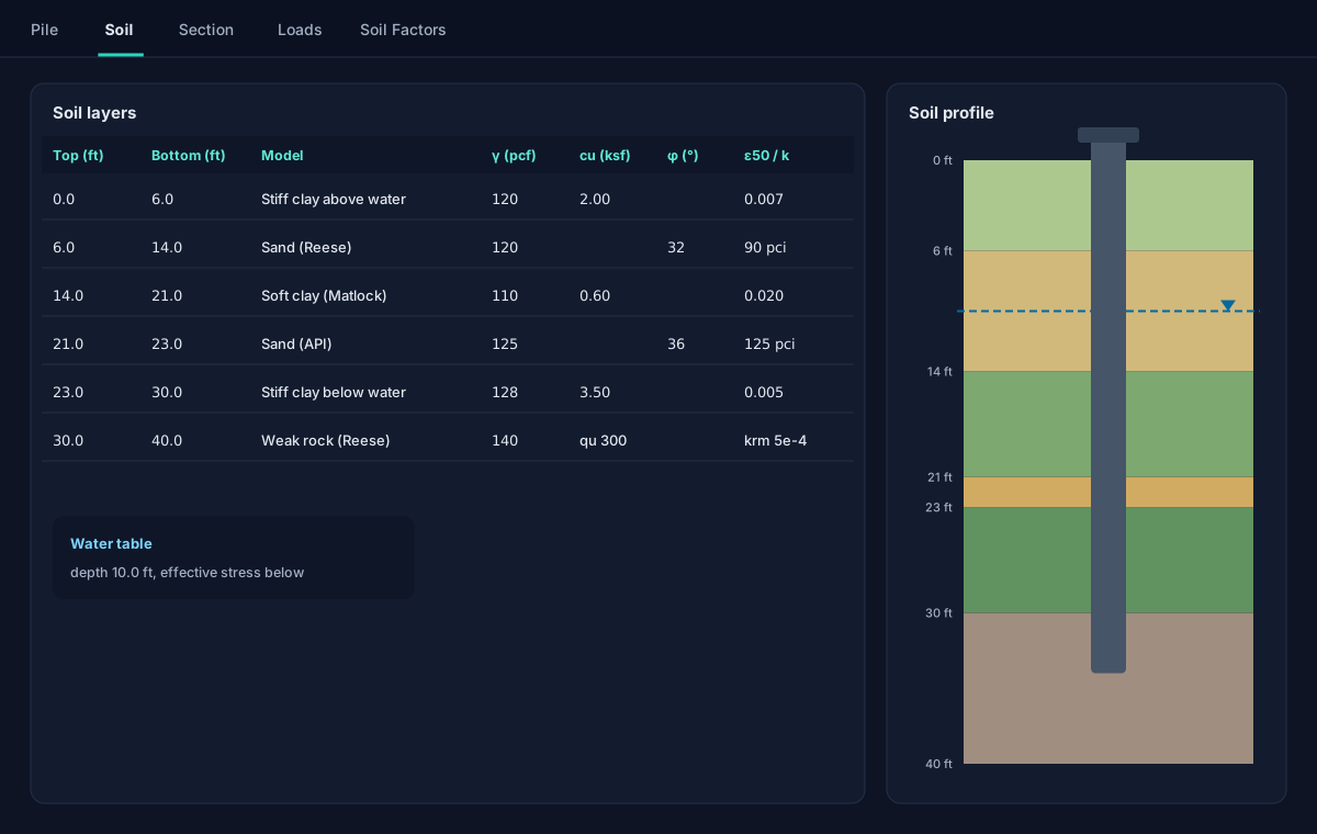
Each layer takes its own model and parameters, and a soil profile drawn to scale beside the grid shows the column the solver sees.

  • Soft clay, Matlock (1970)
  • Stiff clay below the water table, Reese, Cox and Koop (1975)
  • Stiff clay above the water table, Welch and Reese (1972)
  • Sand, Reese, Cox and Koop (1974), the full piecewise curve
  • API sand, API RP 2A-WSD, with its static and cyclic factor
  • Weak rock, Reese (1997); strong rock (vuggy limestone), FHWA-NHI-10-016
  • Linear elastic soil, and your own tabular p-y curves Pro
  • The Georgiadis (1983) correction at layer interfaces, and AASHTO group p-multipliers per pile
  • A water table: buoyant unit weights and effective stress below it, for the soil and the pile's own weight
Soil · Layers and profile
Illustration of the Soil tab: six layers in a grid with their models and parameters, beside a coloured soil profile with a water table and the pile drawn through it.

Axial capacity

Skin friction and end bearing, by the method that fits the pile.

The unit resistances along the shaft and at the tip set the t-z and Q-z springs and the soil capacity checks. A drilled shaft takes the drilled-shaft methods; a driven pile takes the driven-pile methods.

Drilled shafts

Free

FHWA-NHI-10-016

  • Clay, sand and rock side resistance and end bearing aligned with FHWA-NHI-10-016
  • SPT blow counts per sand layer for beta-method side resistance and a correlated end bearing
  • A rock side-resistance method per layer: normal, degraded or caving sockets, or the Colorado DOT claystone methods

Driven piles

Pro

FHWA GEC-12 static methods

  • Nordlund in cohesionless layers and the Tomlinson alpha method in cohesive ones, FHWA's recommended set
  • The effective-stress beta method in either, with your own coefficients or mid-range defaults
  • For an H-pile, the box perimeter and the plugged toe, or the bare steel when you choose

Resistance factors

Free

Per geomaterial, for compression and uplift

  • Distinct ASD or LRFD factors by soil type and by compression or uplift, filled from FHWA presets in one click
  • The FHWA driven-pile static-analysis factors for driven piles Pro
  • The soil capacity checked against the resistance-factored capacity on every combination

Section strength · Free

ACI 318-25 on a Mander-confined fiber section.

A drilled shaft's section is checked at every node for every strength combination, and its stiffness follows the cracking the loads cause.

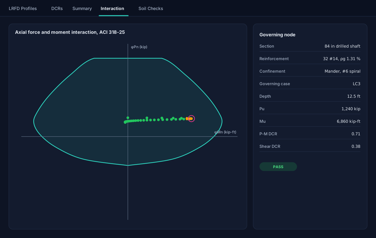
  • Axial force and moment: a full interaction diagram from a fiber section confined by the Mander, Priestley and Park model
  • Shear to ACI 318-25 Section 22.5, with the axial load's contribution
  • Variable stiffness: each node's effective stiffness from the moment-curvature response, within the code's limits
  • Reinforcement by bar count and size or by a target steel ratio, US or metric bars, with the cast-in-place pile steel ratio limits checked
  • Transverse reinforcement in a confined and an ordinary zone, each with its own spacing, in the analysis and in the section sketch
Results · Interaction
Illustration of the Interaction sub-tab: the axial force and moment strength envelope of a drilled shaft with the demand at every node plotted inside it, the governing node circled, and its values listed beside the chart.

Checks · Free

Accuracy, checked from every side.

A converged residual says the solver stopped; it does not say the answer is right. Every solution is examined from the structural, the geotechnical and the numerical side.

Soil mobilization

The soil's capacity, checked on its own

Lateral p-y springs, shaft skin friction and tip bearing are each screened against their ultimate capacity, independently of the section's demand-to-capacity ratio.

Equilibrium audit

Independent of the solver

A separate calculation re-integrates each solution for lateral force, lateral moment with the P-delta moment, and axial force, and flags a blow-up, a deflection beyond the pile's diameter or a degenerate stiffness. Its trace is printed for review.

Governing cases

One per kind of check

Section strength, soil capacity, and deflection and settlement each name their own governing combination, and four status lights show the state of each at a glance.

Load cases · Free

Service and strength combinations, routed for you.

Tagged once

Each combination is marked as a service or an LRFD strength case; section checks read the strength cases and deflection and settlement checks the service ones.

Self-weight in step

A dead-load factor per case keeps the pile's own weight consistent with the combination, such as 0.9D for an uplift check.

From your spreadsheet

Copy load cases to a spreadsheet, edit them there and paste them straight back, with no file to convert.

Driven piles · Pro · New

Precast pretensioned concrete and steel H-piles, each to its own code.

A driven pile is analysed with the same coupled lateral and axial solution as a drilled shaft. What changes is the section, its check and the axial capacity: the FHWA driven-pile static methods of GEC-12 replace the drilled-shaft ones. The drilled shaft stays free.

Section · Driven piles
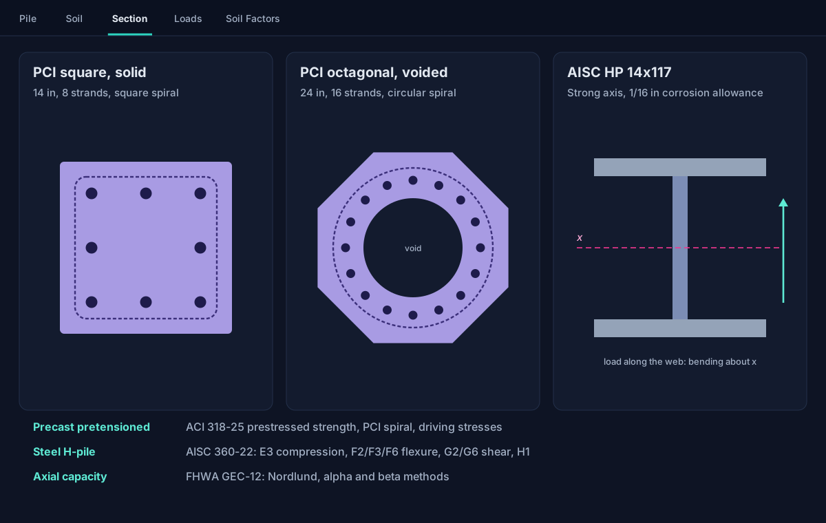
Illustration of three driven pile sections: a solid square precast pile with eight strands inside a square spiral, a voided octagonal precast pile with sixteen strands inside a circular spiral, and a steel HP shape with its strong axis marked, above the standards each is checked to.
Pro

Choose the pile type, and the rest follows.

Pick a precast or an H-pile on the Pile tab and the Section tab offers its sections, the Soil Factors tab its FHWA preset, and the results its checks. A project that already holds a driven pile still opens and runs at any tier; choosing one for another pile needs Pro or the free trial.

  • One bending plane per analysis: for an H-pile you choose the strong or the weak axis, and its stiffness, capacity and soil-face width follow
  • Driving-stress limits reported for information, for comparison with a driveability analysis made elsewhere
  • A project holding a driven pile is saved to the cloud, never to a local file
Precast pretensioned

PCI square and octagonal piles

The PCI standard pile family, solid or voided, with the strand pattern and the spiral formed to it: square around a square pile's strands, circular around an octagonal pile's ring.

  • Interaction diagram by strain compatibility with the ACI 318-25 stress block and unconfined concrete
  • Grade 270 low-relaxation strand by the Devalapura-Tadros power formula
  • The spiral checked against PCI's prescriptive minimum for wire size and pitch
  • Driving-stress limits in compression and tension, from the effective precompression

ACI 318-25 · PCI RP-156-25 · FHWA GEC-12 §8.6.1
Steel H-pile

AISC HP shapes, strong or weak axis

Every HP shape with its exact AISC Shapes Database v16.0 properties, or plates of your own, with an optional corrosion allowance that thins every plate before any property is worked.

  • Compression by AISC 360-22 E3, the embedded length braced by the soil
  • Flexure by F2 and F3 about the strong axis, flange local buckling checked, or F6 about the weak axis
  • Shear by G2 in the web or G6 in the flanges
  • Combined force and moment by H1, so the ratio reads 1.0 where the unity check does

AISC 360-22 · AISC Shapes Database v16.0 · FHWA GEC-12 §8.5.1

Axial capacity

FHWA GEC-12, three methods

The static-analysis methods of FHWA's driven-pile circular feed the same t-z and Q-z springs and the same soil capacity checks as a drilled shaft's.

  • Nordlund in sand, with Thurman's toe coefficients and Meyerhof's limiting toe resistance
  • The Tomlinson alpha method in clay
  • The beta method in either, as an alternative per material
  • FHWA's static-analysis resistance factors in one click

FHWA-NHI-16-009 (GEC-12) Ch. 7 · Table 7-1

Data and reports · Free

Your data, in the formats you already use.

Plain-text projects

Each project is one JSON .lpcj file holding every pile analysis at a site, readable and easy to send to a reviewer.

Spreadsheet round trip

Soil layers and load cases copy out with headers and paste back in; every chart copies as a picture or as its data.

Governing report and CSV

A numbered governing-design report for every run, ready to paste into a submittal, and a CSV export of the results.

Formulas, units, themes

Type a formula after = in any number field and lengths in feet and inches; Imperial or SI display; light or dark.

Several piles, one project

A line of caissons or a tower's four foundations in one project, each pile with its own analysis and its own location; Run All runs them all.

Undo that survives a save

Undo and redo reach back past a save, and Reset returns to the last saved state in one step.

The manual, built in

Help > User's Manual opens the complete manual beside your work: every method, equation, assumption, limit and the validation.

Pro

The capacity to failure, and the report that carries it.

Analysis · Pushover
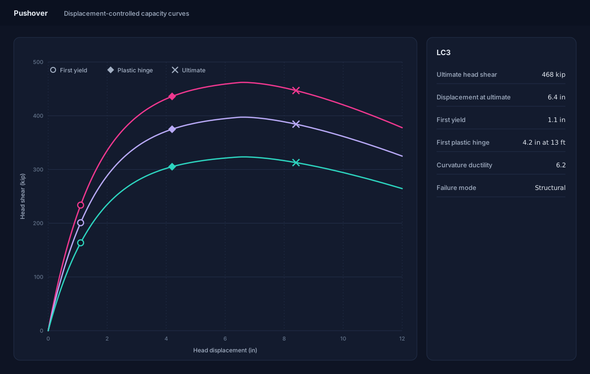
Illustration of the Pushover screen: three capacity curves of head shear against head displacement, each rising to a peak and softening beyond it, with first yield, the first plastic hinge and the ultimate point marked, and the governing case's capacity, ductility and failure mode listed beside them.
Pro

Pushover: the full lateral capacity curve.

For each load case the axial load is held at the case's value while the head is pushed sideways in small displacement steps, so the curve runs through its peak and down the softening branch a load-controlled push cannot reach.

  • The ultimate lateral capacity, and the reserve beyond a given design load
  • First yield and plastic hinges, with the depth where each forms
  • Curvature ductility, and whether the section or the soil fails first
  • The curve starts where the pile actually stands under its moment and axial load
Pro

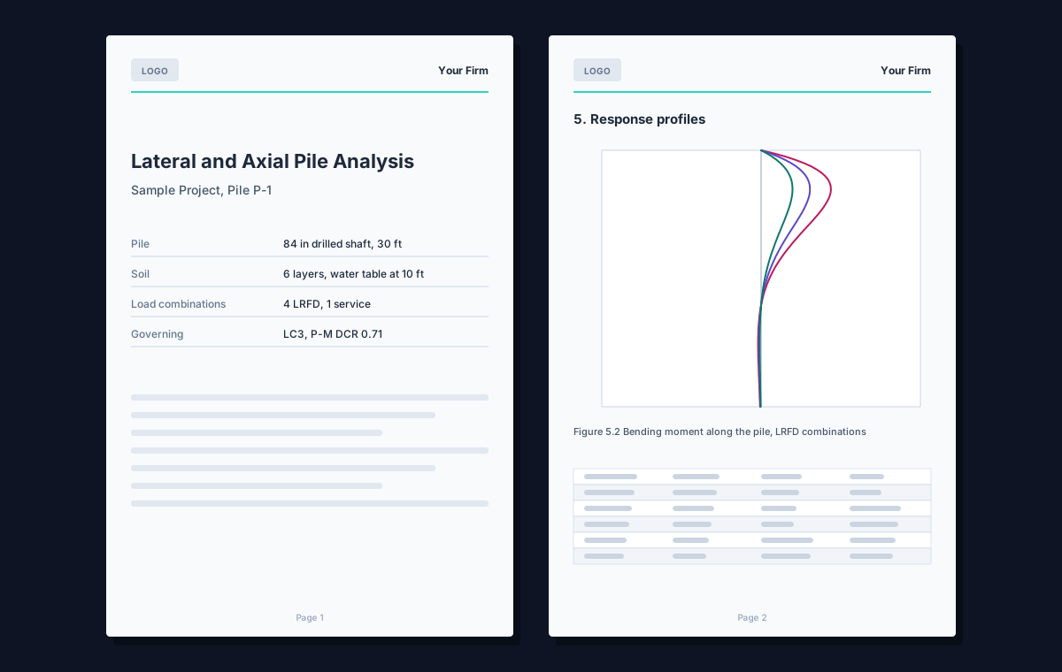
The branded PDF submittal report.

One PDF assembles the complete record of a run, from the cover to the references, written only from the current results.

  • Project, pile, soil, section and load case data
  • The governing summary for section and soil capacity, the response and ratio profiles, and the interaction diagram
  • The soil capacity results and the equilibrium audit, and the pushover when one has been run
  • Your firm's name and logo, the paper size, and the sections you choose, remembered for next time
PDF report
Illustration of two pages of the PDF report: a cover with a logo, the project and the governing result, and a page of response profiles with a table.

Cloud

Optional, never required.

Local project files are the default and work offline without an account. Sign in when you want your projects on any computer, and the Pro tools for the work you repeat.

Cloud projects

Save a project to the cloud under a job and open it on any computer you sign in on.

Version history

Every save is a version you can open and restore; saved versions are kept for six months.

Recycle bin and clients

Deleted projects wait thirty days where you can restore them, and a client list fills in your projects.

Pro

Organization sharing

File a job under your organization so every member can open, edit and run it; whoever is editing is shown to the others.

Pro

p-y and soil libraries

Save a p-y curve or a whole soil column once and load it anywhere: private, shared with your organization, or a soil column published to every PileAxis user.

Pro

Maps and attachments

Your projects and soil models on a map, each pile at its own coordinates, and site boundaries from a shapefile, KML/KMZ or a sketch.

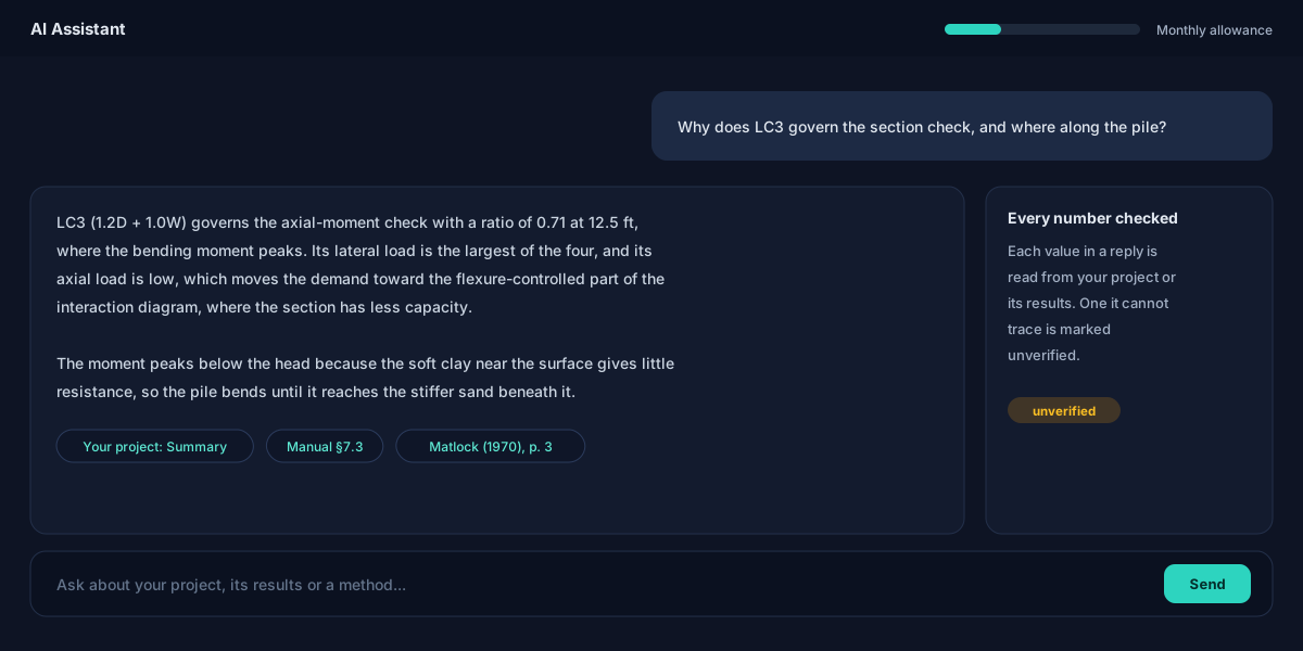
AI Assistant · Pro

Ask about your project in plain words.

The AI Assistant opens in its own window beside the program and answers from your open project: its pile, soil, section and loads, its results and its pushover. It streams its reply, formatted, and says what it is doing while it works.

  • It explains the governing case, a demand-to-capacity ratio, the soil's mobilization or a pushover's failure mode
  • It checks a tabular p-y curve for common entry mistakes
  • It answers how-to and methodology questions from the User's Manual, and cites the source papers behind the methods, opening each at the quoted passage
  • It finds your other cloud projects near this one, measured to each pile, or by pile, soil, section and load properties, or by a description of the work
  • Every number it states is read from your project; one it cannot trace is marked unverified

It reads your project and cannot change it, and it searches only your own projects. Its answers are subject to the same disclaimer as the rest of the program: review by a licensed engineer is required. Use counts against a monthly allowance shown in the chat window.

Illustration of the AI Assistant: the engineer asks why a load case governs the section check; the reply names the case, its ratio and the depth where the moment peaks, explains why, and cites the project's summary, the manual and a source paper, with a note that an untraceable number would be marked unverified.

Limits

What it does not do, said plainly.

So you know what still needs doing elsewhere. The user's manual lists every assumption and every limit.

One pile, one plane

A single pile bending in one plane. Simultaneous biaxial bending is not solved, and rectangular non-prestressed sections are not supported.

Groups through p-multipliers

A pile in a group is approximated by the p-multiplier you enter; a full group interaction matrix is not solved.

Static loading

Cyclic effects enter only through the API sand model's cyclic factor. Time-history dynamic response is outside the scope.

No driveability simulation

Driving-stress limits are reported for information only; a wave-equation driveability analysis is made elsewhere.

No liquefaction or lateral spreading

Liquefaction-induced lateral spreading is outside the scope.

Empirical p-y models

Real soil can depart from the idealized curves; site-specific geotechnical recommendations take precedence over the models and defaults.

Validation

Pinned to published answers.

The methods are checked against closed-form solutions, published reference examples and worked examples, each held by an automated test. The manual's validation chapter gives every case with its numbers.

Closed form

Hetenyi (1946)

A long elastic pile on a Winkler foundation: head deflection within 0.8 % of the closed-form value.

Reference examples

Soft clay and sand

Published reference solutions in Matlock soft clay and Reese sand: head deflection and maximum moment within 3 % in the clay, and within 10 % in the sand.

Field test

Weak rock

Reese's (1997) Islamorada load test: head deflection within 3.3 % of the value Reese reports.

ACI 318-25

Section strength

Pure axial strength within 0.04 % of the hand calculation, and shear with the axial contribution exact.

Models

Mander and stiff clay

Confined concrete across its limiting cases, and three published stiff-clay p-y curves matched point for point.

Driven piles

FHWA worked examples

Nordlund and Tomlinson values reproduced from FHWA's printed examples, PCI section tables, the strand model's published example, and the AISC catalogue's exact properties.

References

The documents behind the checks.

  1. Naik, T.R. and Peyrot, A.H. (1976). Analysis and design of laterally loaded piles and caissons in a layered soil system. ASCE National Structural Engineering Conference.
  2. Matlock, H. (1970). Correlations for design of laterally loaded piles in soft clay. 2nd Offshore Technology Conference, Paper 1204.
  3. Reese, L.C., Cox, W.R. and Koop, F.D. (1974). Analysis of laterally loaded piles in sand. 6th OTC, Paper 2080; (1975) Field testing and analysis of laterally loaded piles in stiff clay, 7th OTC, Paper 2312.
  4. Welch, R.C. and Reese, L.C. (1972). Laterally Loaded Behavior of Drilled Shafts. Research Report 89-10, Center for Highway Research, University of Texas at Austin.
  5. Reese, L.C. (1997). Analysis of laterally loaded piles in weak rock. J. Geotech. and Geoenv. Engrg., ASCE, 123(11).
  6. Georgiadis, M. (1983). Development of p-y curves for layered soils. Geotechnical Practice in Offshore Engineering, ASCE.
  7. API (2010). RP 2A-WSD, Recommended Practice for Planning, Designing and Constructing Fixed Offshore Platforms, 22nd ed.
  8. Brown, D.A., Turner, J.P. and Castelli, R.J. (2010). Drilled Shafts: Construction Procedures and LRFD Design Methods. FHWA-NHI-10-016 (GEC-10).
  9. Hannigan, P.J. et al. (2016). Design and Construction of Driven Pile Foundations. FHWA-NHI-16-009 and -010 (GEC-12).
  10. Mander, J.B., Priestley, M.J.N. and Park, R. (1988). Theoretical stress-strain model for confined concrete. J. Struct. Engrg., ASCE, 114(8).
  11. ACI Committee 318 (2025). ACI CODE-318-25, Building Code Requirements for Structural Concrete and Commentary.
  12. ANSI/AISC 360-22 (2022). Specification for Structural Steel Buildings; AISC Shapes Database v16.0 (2023).
  13. PCI Prestressed Concrete Piling Committee (2025). Recommended practice for design, manufacture, and installation of prestressed concrete piling, RP-156-25. PCI Journal, 70(6).
  14. Devalapura, R.K. and Tadros, M.K. (1992). Stress-strain modeling of 270 ksi low-relaxation prestressing strands. PCI Journal, March-April 1992.
  15. AASHTO (2020). AASHTO LRFD Bridge Design Specifications, 9th ed.

Run a pile you already know the answer to.

Download PileAxis free, with no account, and check it against a case you trust. Then sign in to try the Pro features free.