New Driven piles: precast pretensioned concrete and steel H-piles, with FHWA driven-pile axial capacity. See what is new →

Lateral & axial pile analysis · Windows

Piles and drilled shafts, analysed end to end.

PileAxis analyses a single drilled shaft, precast pretensioned pile or steel H-pile under combined axial and lateral loads in layered soil. It solves the p-y response coupled with the axial response for every load combination, checks the section to ACI 318-25 or AISC 360-22, and audits the soil and the equilibrium independently, with the reference behind every result.

  • No sign-up
  • Drilled shafts free
  • Works offline
  • Windows 10 & 11
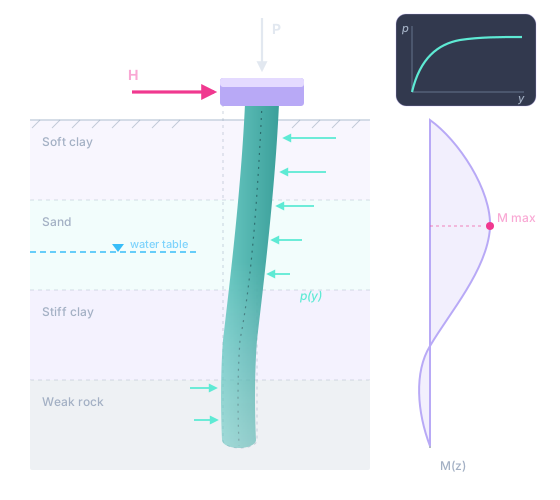
Illustration of a drilled shaft under a cap in layered soil, pushed sideways by a lateral load and pressed down by an axial load: the shaft on its deflected shape, the soil pushing back on it, a p-y curve, and the bending moment along its length with its maximum marked.
Sample Project, Pile P-1 — PileAxis
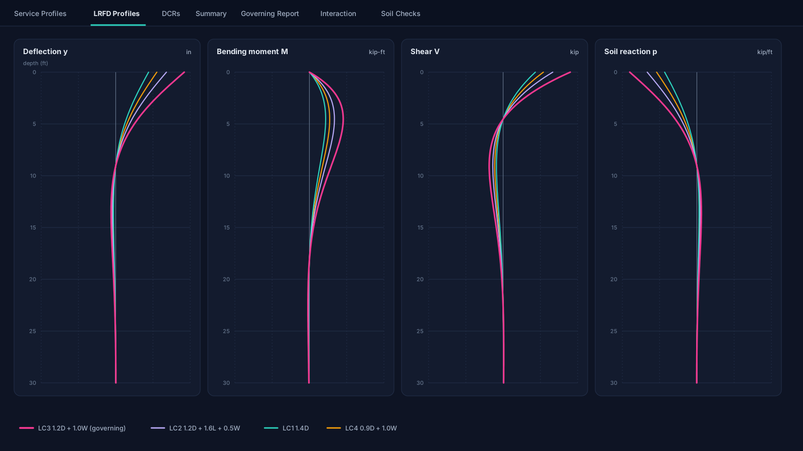
Illustration of the Results tab's LRFD profiles: deflection, bending moment, shear and soil reaction plotted against depth along a 30 ft pile for four load combinations, the governing one drawn heavier.
Free · no account

Download it and run your first pile. No sign‑up. No subscription.

Drilled-shaft analysis, the section and soil checks, the governing report and projects saved on your own computer are free. They need no account, and they work offline. Sign in only when you want the cloud or the Pro features.

  • No account to create

    Install, open and analyse. Nothing asks for an email address before you can work.

  • No trial clock on the free part

    The free capabilities are not a time-limited trial. Nothing counts down and there is nothing to cancel.

  • Works offline

    The analysis runs on your computer. No connection is needed to build a pile, run it or read the results.

  • Your work stays yours

    No telemetry, analytics or advertising. Local projects are plain-text .lpcj files you keep.

Three pile systems

Drilled, precast or steel, in one workflow.

Choose the pile system for each analysis. Whichever it is, you build one model, run every load combination, and read the soil's response and the section's demand-to-capacity ratios side by side.

  • Free

    Drilled shafts and caissons

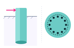
    The circular cast-in-place reinforced concrete pier, checked to ACI 318-25 on a Mander-confined fiber section.

  • Pro · New

    Precast pretensioned piles

    PCI square and octagonal piles, solid or voided, checked to ACI 318-25's prestressed provisions with PCI's spiral and driving-stress checks.

  • Pro · New

    Steel H-piles

    AISC HP shapes from the catalogue or your own plates, bent about the strong or the weak axis, checked to AISC 360-22.

One pile, one bending plane, static loading. PileAxis analyses a single pile in one plane. A pile in a group is approximated through the p-multipliers you enter, and cyclic loading through the API sand model's cyclic factor; the limits are stated plainly on the features page.

Built on the documents you sign against

  • ACI 318-25
  • AISC 360-22
  • FHWA GEC-12
  • FHWA NHI-10-016
  • PCI RP-156-25
  • API RP 2A-WSD
  • AASHTO LRFD 10.7.2.4
  • AISC Shapes Database v16.0

What it does, free

Every check, from one converged solution.

Every load combination is solved once and then examined from every side: the section's strength, the soil's capacity, the deflection and settlement, and an equilibrium audit that does not trust the solver.

Soil

Layered soil that follows the literature.

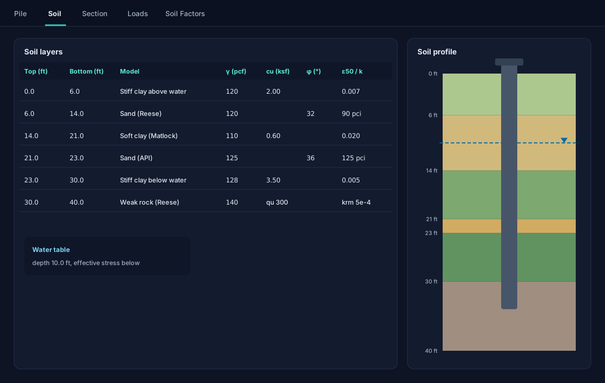
Build the soil column layer by layer from eight built-in p-y models, each with its own parameters, under a water table that sets the effective stress for you.

  • Soft clay (Matlock), stiff clay below and above the water table, sand (the full Reese curve), API sand, weak rock and strong rock, and a linear soil
  • The Georgiadis correction at layer interfaces, and AASHTO group p-multipliers per pile
  • Buoyant unit weights and effective stress below the water table, worked for you
  • Copy a soil column to a spreadsheet, edit it there and paste it back
  • Matlock (1970)
  • Reese et al. (1974, 1975)
  • Georgiadis (1983)
Soil · Layers and profile
Illustration of the Soil tab: six layers in a grid with their models and parameters, beside a coloured soil profile with a water table and the pile drawn through it.

Section strength

ACI 318-25 on a Mander-confined fiber section.

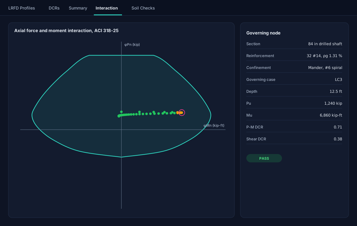
A drilled shaft is checked at every node of the pile, for every strength combination: a full axial-moment interaction diagram and the shear check with the axial load's contribution.

  • The stiffness of each node taken from the section's moment-curvature response, so a cracked pile is analysed as a cracked pile
  • Reinforcement by bar count and size or by a target steel ratio
  • Confined and ordinary zones of transverse reinforcement, each with its own spacing
  • The demand at every node plotted against the interaction diagram
  • ACI 318-25 §22.4
  • §22.5
  • §13.3.2.1
  • Mander et al. (1988)
Results · Interaction
Illustration of the Interaction sub-tab: the axial force and moment strength envelope of a drilled shaft with the demand at every node plotted inside it, the governing node circled, and its values listed beside the chart.

Checks

A governing case for each kind of check, not one number for all.

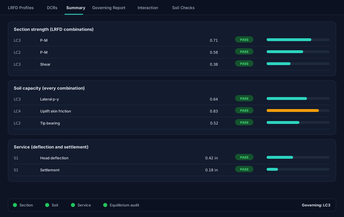
The section is judged on the strength combinations, the soil's capacity on every combination against a resistance-factored capacity, and deflection and settlement on the service combinations, each with its own governing case.

  • Lateral p-y springs, shaft skin friction and tip bearing each screened against their ultimate capacity
  • Every converged solution re-integrated for force and moment balance, the P-delta moment included
  • Status lights for the section, the soil, service and the equilibrium audit
  • A numbered governing report and CSV export for every run
Results · Summary
Illustration of the Summary: three tables, for section strength, soil capacity and service, each row a check with its load case, its ratio and a pass mark, above four green status lights.

Lateral and axial, coupled

A finite-difference beam on nonlinear p-y springs, coupled with t-z and Q-z springs, so the axial load's effect on bending is carried through.

An audit that does not trust the solver

Each solution is checked for equilibrium by a separate calculation, so a sign or discretization error cannot hide behind a converged residual.

Service and LRFD, routed for you

Tag each combination once; strength checks read the factored ones and deflection checks the service ones, all solved in parallel.

Spreadsheet in, spreadsheet out

Soil layers and load cases copy to a spreadsheet and paste back; every chart copies as a picture or as its data.

The full manual, built in

Methods, equations, assumptions, limits and the validation, written so you can verify the engineering yourself, open beside your work.

The cloud, when you want it

Sign in with an email address for cloud projects on any computer, with version history, a recycle bin and a client list.

Pro

Driven piles, pushover, and the report that goes in the submittal.

The Pro features take the analysis further: more pile systems, the pile's capacity curve to failure, a branded report, an assistant that reads your project, and cloud libraries and maps for the work you repeat.

Free trial Sign in with an email address and every Pro feature opens for a free trial, counted from your first sign-in to PileAxis. Nothing is charged and there are no in-app purchases.
Section · Driven piles
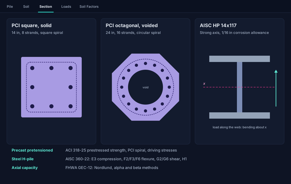
Illustration of three driven pile sections: a solid square precast pile with eight strands inside a square spiral, a voided octagonal precast pile with sixteen strands inside a circular spiral, and a steel HP shape with its strong axis marked, above the standards each is checked to.
Pro · New

Driven piles: precast pretensioned concrete and steel H-piles.

Analyse a driven pile with the same coupled lateral and axial solution as a drilled shaft. Its axial capacity comes from the FHWA driven-pile static methods, and its section is checked to the code that governs it.

  • PCI square and octagonal piles, solid or voided, to ACI 318-25's prestressed provisions, with PCI's spiral check
  • AISC HP shapes or custom plates, strong or weak axis, to AISC 360-22: compression, flexure, shear and their interaction
  • Axial capacity by FHWA GEC-12: Nordlund in sand, the alpha method in clay, or the beta method in either
  • Driving-stress limits reported for information, and the FHWA driven-pile resistance factors in one click
Pro

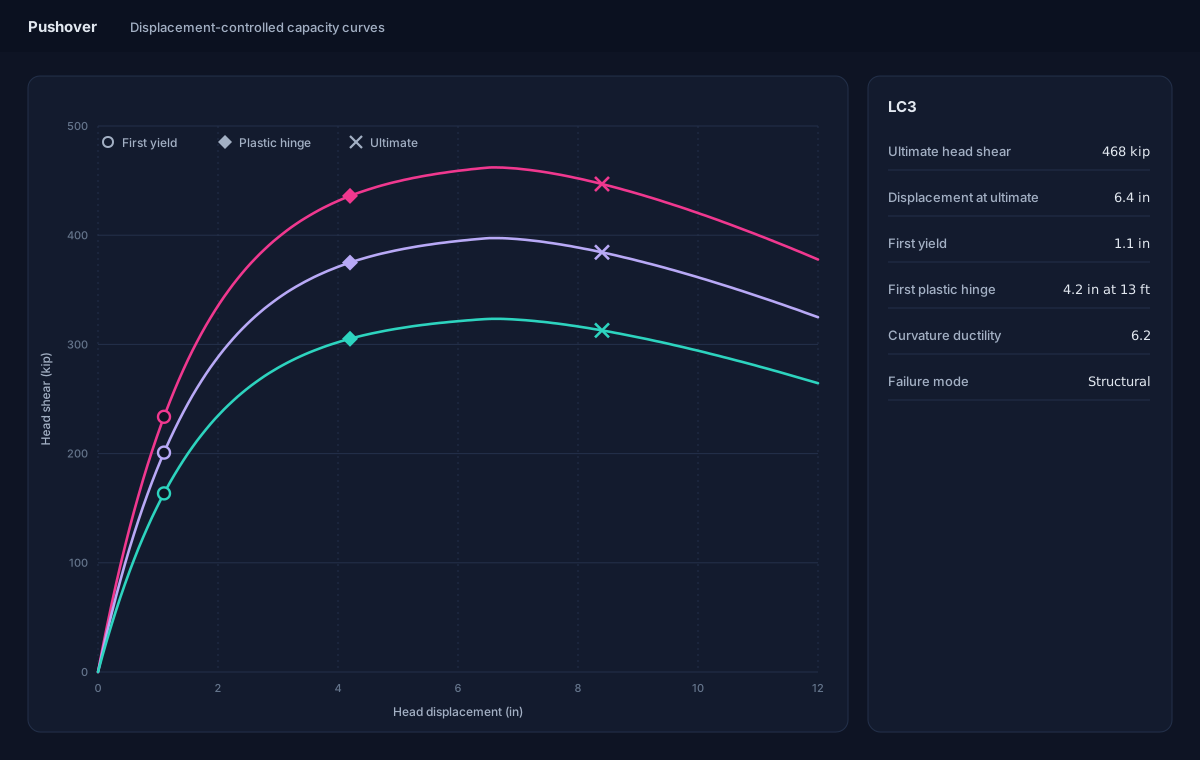
Push each load case to failure.

The pushover traces each load case's full lateral capacity curve, pushing the head by displacement so the curve runs past its peak, with the axial load held at the case's own value.

  • The ultimate lateral capacity and the reserve beyond your design load
  • First yield and plastic hinges, marked on the curve with their depths
  • Curvature ductility, and whether the section or the soil gives way first
Analysis · Pushover
Illustration of the Pushover screen: three capacity curves of head shear against head displacement, each rising to a peak and softening beyond it, with first yield, the first plastic hinge and the ultimate point marked, and the governing case's capacity, ductility and failure mode listed beside them.
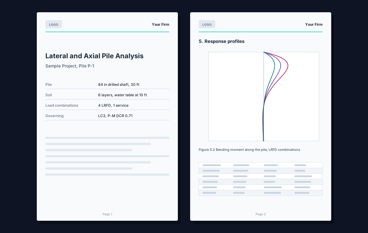
Illustration of two pages of the PDF report: a cover with a logo, the project and the governing result, and a page of response profiles with a table.
Pro

The PDF submittal report

One PDF with the inputs, the governing summary, the profiles, the interaction diagram, the soil checks, the equilibrium audit and the references.

  • Your firm's name and logo on the cover and every page
  • Letter, Legal, A4 or Tabloid, with the sections you choose
  • The pushover included when one has been run
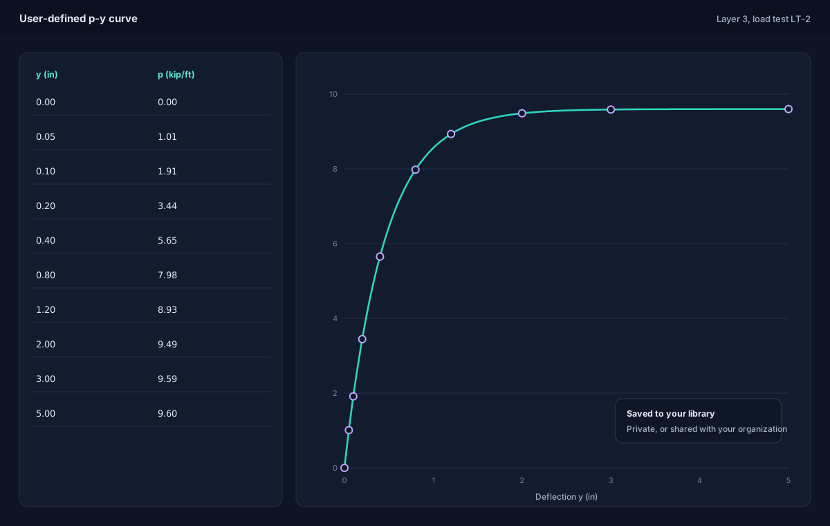
Illustration of the user-defined p-y curve editor: a table of deflection and soil reaction points beside the curve they make.
Pro

Your own p-y curves, and libraries

Enter a p-y curve point by point, from a load test or a geotechnical report, and keep curves and whole soil columns in cloud libraries.

  • Tabular p-y curves for any layer
  • Libraries kept private, shared with your organization, or a soil column published to every PileAxis user
  • Load a saved soil column into a new project in one step
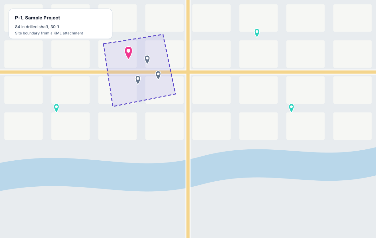
Illustration of the project map: pile markers on a site, one highlighted with its name, inside a site boundary drawn from an attachment.
Pro

Maps and site boundaries

See your cloud projects and soil models on a map, place each pile where it stands, and draw the site's boundary from a file or by hand.

  • Street map or aerial imagery
  • Shapefile and KML/KMZ attachments
  • Address and location lookup

Share with your organization

File a project under your organization so every member can open, edit and run it; whoever is editing is shown to the others.

An AI Assistant that reads your project

Ask why a case governs or how a method works, and get an answer read from your own project, with its sources. More below.

Pro · AI Assistant

An assistant grounded in your project, not in guesses.

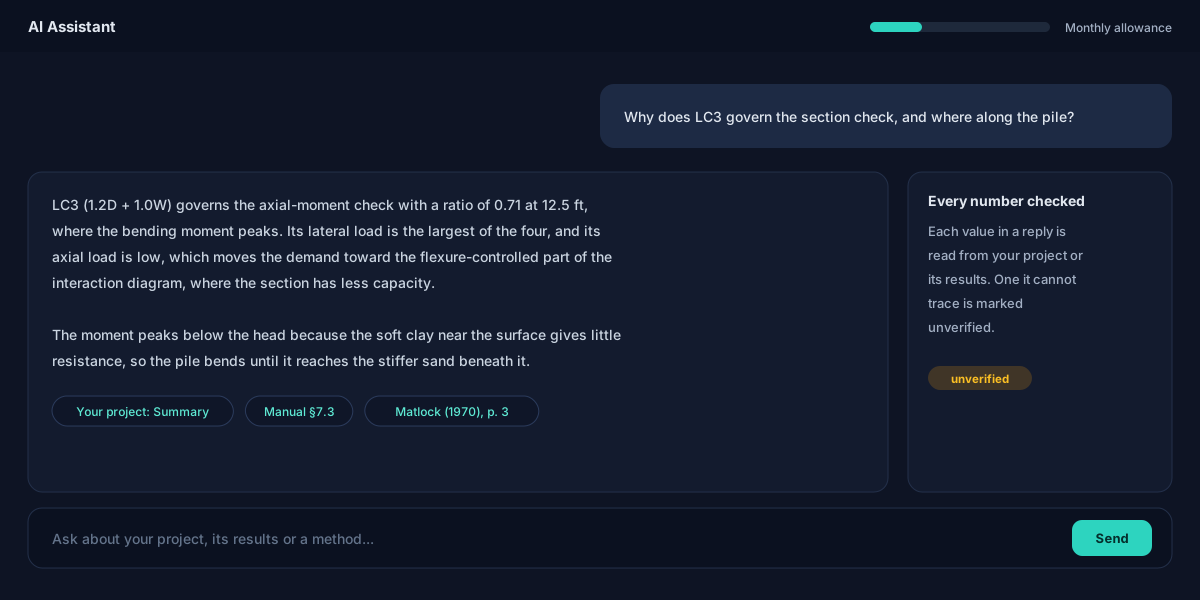
The AI Assistant is a chat window beside the program. It reads your pile, soil, section and loads, your results and your pushover, and answers from them: why a case governs, what a ratio means, how a method works, and where to look next.

  • Every number it states is read from your project or its results; one it cannot trace is marked unverified in the chat
  • Methods and how-to questions are answered from the same User's Manual you can open yourself
  • It searches the published papers behind the methods and cites the passage, a click from the source
  • It finds your other cloud projects by distance to each pile, by pile, soil or load properties, or by a description of the work

The assistant reads your project and cannot change it. Its answers carry the program's engineering disclaimer: review by a licensed engineer is required. Your question and the project data it needs are sent to Microsoft's Azure AI service to answer it; we count your usage against a monthly allowance and do not keep the conversation. See the privacy policy.

Illustration of the AI Assistant: the engineer asks why a load case governs the section check; the reply names the case, its ratio and the depth where the moment peaks, explains why, and cites the project's summary, the manual and a source paper, with a note that an untraceable number would be marked unverified.

Plans

Start free. Sign in when you want more.

The drilled-shaft analysis costs nothing and asks for nothing. An account adds the cloud, and a free trial of every Pro feature.

No sign-up

Free

$0no account

Everything you need to analyse and check a drilled shaft on your own computer.

  • Coupled lateral and axial analysis
  • Eight p-y soil models, water table, p-multipliers
  • ACI 318-25 section design
  • Soil capacity and equilibrium checks
  • Governing report and CSV export
  • Local project files, offline
Download free

Signed in

$0sign in with email

Everything in Free, plus the cloud, and a free trial of every Pro feature from your first sign-in.

  • Cloud projects, on any computer
  • Version history and a recycle bin
  • A client list for your projects
  • A free trial of every Pro feature
How signing in works
Pro

Pro

Soonpricing to be announced

Every Pro feature without a time limit, for engineers and firms. Try all of it free today.

  • Driven precast and steel H-piles
  • Pushover capacity curves
  • The PDF submittal report
  • The AI Assistant
  • Tabular p-y curves and cloud libraries
  • Maps, attachments and organization sharing
Try Pro free

Download

Get PileAxis for Windows.

Free to download and free to use, with no account. PileAxis is coming to the Microsoft Store, which will install it and keep it up to date.

Coming soon to theMicrosoft Store
Until then, the current release installs from our download page and updates itself. Install the current release

Free · no account needed · Windows 10 or 11, 64-bit

  • SystemWindows 10 or 1164-bit
  • Processorx64 or ARM6432-bit x86 is not supported
  • Memory8 GB minimum16 GB for long runs with many load cases
  • Display1280 × 800 or larger1920 × 1080 recommended
  • Runtime.NET 10 DesktopFor the current release; free from Microsoft
  • InternetOnly when signed inFor the cloud, maps, the assistant and Pro

Feedback

Found a bug? Have an idea? Tell us in the open.

PileAxis's issue tracker is public on GitHub: see what has been reported, follow what is being fixed, and vote for what should come next.

Report a bug

Something wrong, a number that looks off, a crash? Tell us what happened and how to see it again.

Open a bug report

Request a feature

A soil model, a pile type, a standard you need, a step it could save you. Ideas from practice shape what comes next.

Suggest a feature

Write privately

Confidential project data, engineering questions, licensing or your account: email us rather than posting in public.

admin@ramisoftsolutions.com

An engineering aid, not a substitute for engineering judgement

The soil is represented by the p-y, t-z and Q-z models and the parameters you enter; site-specific geotechnical recommendations take precedence. Results must be reviewed by a licensed engineer before they are relied on in a stamped submittal. See the terms of use.